| CPC F02C 7/18 (2013.01) [F01D 5/186 (2013.01); F01D 9/02 (2013.01); F01D 9/065 (2013.01); F01D 25/12 (2013.01); F02C 3/14 (2013.01); F02C 7/28 (2013.01); F16J 15/02 (2013.01); F05D 2220/32 (2013.01); F05D 2240/55 (2013.01); F05D 2240/81 (2013.01); F05D 2260/20 (2013.01); F05D 2260/201 (2013.01); F05D 2260/202 (2013.01)] | 18 Claims |

|
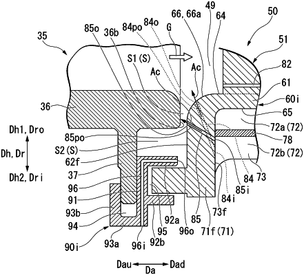
1. A turbine vane comprising:
a blade body which forms a blade profile, the blade body having a first end facing in a first height direction of the blade body and a second end facing in a second height direction of the blade body, the first height direction and the second height direction being opposite directions; and
a shroud which is provided at the second end of the blade body,
wherein the shroud includes:
a gas path surface which faces toward the first height direction and is in contact with a combustion gas,
a rear end surface which is directed toward an existing side of a trailing edge with respect to a leading edge of the blade body and a downstream side in a flow of the combustion gas and is located on the downstream side in relation to the blade body,
a front end surface which is directed toward an upstream side opposite to the downstream side and is located on the upstream side in relation to the blade body,
a pressure side end surface which connects the front end surface and the rear end surface and in which a pressure side of the blade body exists with reference to a camber line of the blade body, the pressure side end surface being located on the pressure side in relation to the blade body,
a suction side end surface which connects the front end surface and the rear end surface and in which a suction side of the blade body exists with reference to the camber line of the blade body, the suction side end surface being located on the suction side in relation to the blade body,
a front end corner portion which is a corner portion between the gas path surface and the front end surface,
a cavity defining surface which is formed in a region surrounded by the front end surface, the rear end surface, the pressure side end surface, and the suction side end surface, and defines a cavity into which a cooling air flows,
a first air passage in which the cooling air flows, and
a second air passage in which the cooling air flows,
wherein the first air passage includes a first inlet opened at the cavity defining surface and a first outlet opened at the front end corner portion,
wherein the second air passage includes a second inlet opened at the cavity defining surface and a second outlet opened at the front end surface,
wherein the first inlet is positioned farther in the second height direction than a position of the second inlet in the second height direction, and
wherein the pressure side end surface and the suction side end surface are arranged on opposite sides of the shroud with respect to a lateral direction, and the first air passage and the second air passage cross each other when viewed in the lateral direction.
|