| CPC F02C 6/20 (2013.01) [B23K 20/10 (2013.01); F02C 7/32 (2013.01); H01L 23/40 (2013.01); H05K 7/20927 (2013.01); B23K 2101/001 (2018.08); B64D 2027/026 (2013.01); F05D 2220/323 (2013.01); F05D 2220/76 (2013.01); H01G 9/0003 (2013.01)] | 18 Claims |

|
1. A propulsion system for use with an aircraft, the propulsion system comprising:
a gas turbine engine including a compressor, a combustor, and a turbine,
an electric power system including a generator coupled to the gas turbine engine to generate electrical energy, power electronics connected to the generator to receive the electrical energy from the generator, wherein the power electronics are configured to convert the electrical energy for transferring the electrical energy between components of the electric power system, and a motor configured to produce rotational energy in response to receiving electric energy from the power electronics, and
at least one propulsor configured to use rotational energy received from the motor of the electric power system to generate thrust for propelling the aircraft,
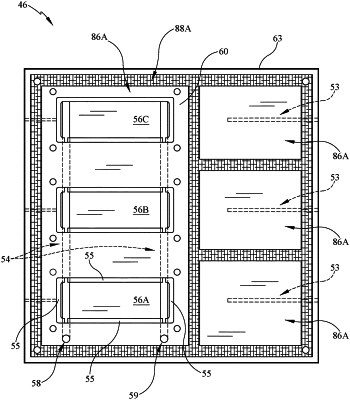
wherein the power electronics includes electrical components and a housing integrated with thermal management features and shock load reinforcement using ultrasonic additive manufacturing to protect the electrical components, the housing including (i) a base comprising a composite material of a first metallic material and ceramic fibers and the base formed to include a cooling passageway that extends there-through to transfer a flow of cooling fluid through the base to cool the electrical components mounted to the base, (ii) a cover comprising a second metallic material that extends over the electrical components mounted to the base, and (iii) vibration dampers that extend between and interconnect the base to the aircraft to minimize the vibrations transferred to the base and the cover,
wherein the base of the housing includes a base plate comprising the composite material of the first metallic material and ceramic fibers and formed to define the cooling passageway, a heat shield comprising a third metallic material having a thermal resistance greater than the first metallic material that extends around an outer surface of the base plate to protect the base plate from high external temperatures, and at least one heat transfer pedestal located in a cavity formed in the base plate that is in fluid communication with the cooling passageway,
wherein the base plate has first localized areas of the first metallic material that are free of ceramic fibers and second localized areas of the ceramic fibers that extend around the first localized areas of the first metallic material on the base plate to provide increased stiffness to the base plate, and
wherein the electrical components are coupled to the base plate at the first localized areas and the cooling passageway is located in one of the first localized areas of the first metallic material on the base plate.
|