| CPC B64C 25/44 (2013.01) [F16D 55/36 (2013.01); F16D 65/123 (2013.01); F16D 65/18 (2013.01); F16D 2055/0058 (2013.01); F16D 2065/132 (2013.01); F16D 2065/1324 (2013.01); F16D 2065/1364 (2013.01); F16D 2065/1376 (2013.01); F16D 2200/0021 (2013.01); F16D 2200/0052 (2013.01)] | 20 Claims |

|
1. A braking arrangement, comprising:
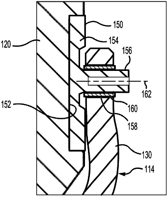
a torque plate comprising a torque tube and a back leg;
an end plate comprising a torque pocket;
a torque button comprising a head portion and a shaft portion, wherein the head portion is configured to extend at least partially into the torque pocket and the shaft portion is configured to extend through an aperture disposed in the back leg; and
a bushing configured to be removably coupled between the shaft portion of the torque button and the back leg of the torque plate.
|