| CPC B41J 2/1433 (2013.01) | 18 Claims |

|
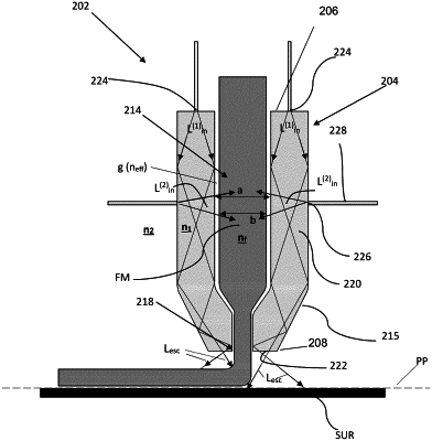
1. A nozzle structure for use in a print head for discharging drops of a printing material onto a substrate located in a printing plane, the nozzle structure comprising:
a tubular member having a distal part by which it faces the printing plane when in operation, said tubular member defining an elongated inner cavity along the length of the tubular member for placement of a filament of the printing material in said inner cavity, said tubular member being configured for light propagation through at least a portion thereof, said tubular member comprising light input ports on the proximal part thereof and being configured for light propagation therethrough along a general propagation direction from the proximal part to the distal part; wherein
the light input ports are configured for directing diverging input light beam towards inner surfaces of the tubular member with a predetermined incidence onto said inner surfaces;
the tubular member comprises an elongated tube portion and a distal tip portion at the distal part of the tubular member,
the elongated tube portion of the tubular member is configured and operable as a light guide for trapping input light, entering said elongated tube portion via the light input ports at the proximal part of the tubular member, and guiding the trapped light propagation along the tubular member by reflections from inner surfaces of the tubular member, thereby continuously transferring light to successive regions of said elongated inner cavity from the proximal part of the tubular member towards the distal part thereof; and
distal tip portion of the tubular member has a cross-sectional geometry different from that of the elongated tube portion to affect light reflections from the inner surfaces of the tubular member and allow the trapped light to escape through the distal part of the tubular member towards the printing plane, thereby interacting with and heating a location on the printing plane facing the distal part; and
wherein said tubular member is made of a material with a refractive index substantially matching a refractive index of the filament material.
|