| CPC B23Q 1/70 (2013.01) [B23Q 17/005 (2013.01); B23Q 17/22 (2013.01); B23Q 2220/006 (2013.01); Y10T 409/309352 (2015.01)] | 6 Claims |

|
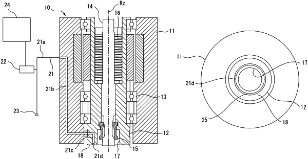
1. A main spindle device of a machine tool using compressed air to confirm seating of a tool holder, the main spindle device comprising:
a main spindle having a distal end face which a flange end face of the tool holder closely contacts;
an annular recess formed at the distal end face of the main spindle so as to be covered by the flange end face of the tool holder;
an air supply flow channel connecting with the annular recess and supplying the annular recess with compressed air;
a compressed air source supplying air to the air supply flow channel; and
a pressure detector detecting pressure of the compressed air inside the air supply flow channel,
wherein the annular recess has a first section and a second section, wherein the first section has a first bottom surface spaced from the distal end face of the main spindle, and the second section has a second bottom surface spaced from the distal end face of the main spindle,
wherein a distance between the second bottom surface and the distal end face of the main spindle is greater than a distance between the first bottom surface and the distal end face of the main spindle, the air supply flow channel opening at the second section.
|