|
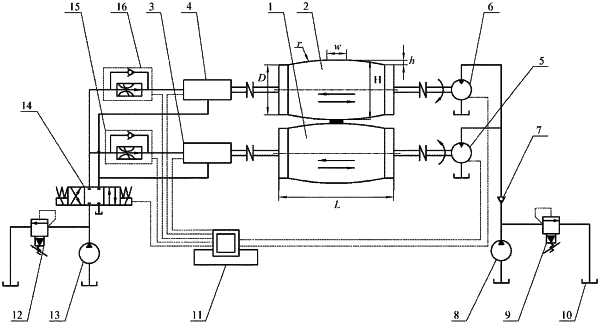
1. A transverse vibration rolling system for a double-layer metal composite ultra-thin strip, comprising: a first roll (1), a second roll (2), a first hydraulic vibrator (3), a second hydraulic vibrator (4), a first hydraulic motor (5), a second hydraulic motor (6), a check valve (7), a first hydraulic pump (8), a first overflow valve (9), an oil tank (10), a controller (11), a second overflow valve (12), a second hydraulic pump (13), an electromagnetic reversing valve (14), a first speed control valve (15), and a second speed control valve (16); wherein the first roll (1) and the second roll (2) have a cylindrical structure protruding from a middle part; hydraulic oil in the oil tank (10) is pumped out by the first hydraulic pump (8), wherein a part of the hydraulic oil flows back to the oil tank (10) after being regulated by the first overflow valve (9) which controls an oil pressure, and the other part of the hydraulic oil pumped by the first hydraulic pump (8) enters the first hydraulic motor (5) and the second hydraulic motor (6) through the check valve (7); the hydraulic oil in the oil tank (10) is also pumped out by the second hydraulic pump (13), wherein a part of the hydraulic oil flows back to the oil tank (10) through the second overflow valve (12) which control the oil pressure, and the other part of the hydraulic oil pumped by the second hydraulic pump (13) enters the first hydraulic vibrator (3) and the second hydraulic vibrator (4) after passing through the electromagnetic reversing valve (14) as well as the first speed control valve (15) and the second speed control valve (16); the first hydraulic motor (5) and the second hydraulic motor (6) are connected to one end of the first roll (1) and one end of the second roll (2) respectively through couplings, so as to facilitate rotation of the first roll (1) and the second roll (2); the first hydraulic vibrator (3) and the second hydraulic vibrator (4) are connected to the other end of the first roll (1) and the other end of the second roll (2) respectively through couplings, so as to drive the first roll (1) and the second roll (2) to vibrate laterally; the controller (11) uses electric signals to control rotation speeds of the first hydraulic motor (5) and the second hydraulic motor (6), vibration frequencies of the first hydraulic vibrator (3) and the second hydraulic vibrator (4), reversing of the electromagnetic reversing valve (14), and flow rates of the first speed control valve (15) and the second speed control valve (16), thereby coordinating movements of the whole system; oil outlets of the first hydraulic motor (5), the second hydraulic motor (6) and the first hydraulic pump (8) are all connected to the oil tank (10) to realize oil return; oil return ports of the first hydraulic vibrator (3) and the second hydraulic vibrator (4) are both connected to the electromagnetic reversing valve (14) to realize oil return.
|
