| CPC A61M 5/31576 (2013.01) [A61M 5/31513 (2013.01); A61M 5/31528 (2013.01); A61M 5/31548 (2013.01); B05C 5/0225 (2013.01); B05C 11/1031 (2013.01); A61M 2005/3128 (2013.01); B05C 5/0233 (2013.01); B05D 1/26 (2013.01)] | 20 Claims |

|
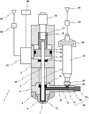
1. A liquid-material discharge device, comprising:
a discharging member having a rod-shaped body;
a liquid chamber wider than the discharging member, in which a tip portion of the discharging member is disposed;
a discharge port communicating with the liquid chamber;
a liquid feed path having an opening provided in the liquid chamber and that makes the liquid chamber communicate with a liquid-material reservoir; and
a driving device configured to drive the discharging member,
wherein the liquid-material discharge device comprises a discharge amount adjustment member positioned at the liquid feed path to adjust resistance in the liquid feed path, and a member position adjustment mechanism configured to shift and fix a position of the discharge amount adjustment member within the liquid feed path,
wherein the member position adjustment mechanism changes the position of the discharge amount adjustment member so that a discharge amount is able to be adjusted.
|