| CPC A45B 9/04 (2013.01) [A45B 9/02 (2013.01); A61H 3/0277 (2013.01); A61H 3/0288 (2013.01)] | 9 Claims |

|
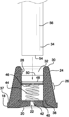
1. A shock-absorbing cane tip apparatus comprising:
a tip base having a base top side, a base bottom side, and a base perimeter;
a tip sidewall coupled to the tip base, the tip sidewall having a sidewall outer face, a sidewall inner face, and a sidewall top rim, the sidewall inner face defining a cane cavity configured to slidingly receive a tip end of a cane;
a bottom plate coupled to the tip base, the bottom plate being coupled within the cane cavity;
a compression spring coupled to the bottom plate, the compression spring being oriented perpendicular to the base top side;
a top plate coupled to the compression spring, the top plate having a top plate diameter less than a cavity diameter of the cane cavity, the top plate being configured to engage a distal end of the tip end of the cane and compress the compression spring when weight is pushed onto the cane; and
the tip sidewall and the base perimeter defining an outer lip of the base top side therebetween.
|