| CPC H02S 20/32 (2014.12) [F15B 15/20 (2013.01); F16F 9/0254 (2013.01); F16F 9/185 (2013.01); F16F 9/34 (2013.01); F16F 9/369 (2013.01); F16F 9/50 (2013.01); F16M 11/10 (2013.01); F24S 30/425 (2018.05); F24S 40/00 (2018.05); H02S 30/10 (2014.12); H02S 40/30 (2014.12); H02S 50/00 (2013.01); F16F 9/10 (2013.01); F16F 9/103 (2013.01); F16F 9/44 (2013.01); F16F 9/49 (2013.01); F16F 2222/12 (2013.01); F16F 2228/066 (2013.01); F16F 2230/0041 (2013.01); F16F 2230/30 (2013.01); F16F 2232/08 (2013.01); F16F 2234/02 (2013.01); F24S 2030/115 (2018.05); F24S 2030/19 (2018.05); H02S 99/00 (2013.01)] | 20 Claims |
|
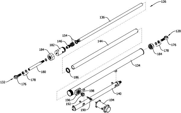
1. A solar tracker system comprising:
a torque tube;
a column supporting the torque tube;
a solar panel connected to the torque tube; and
a damper assembly having a first end pivotably connected to the torque tube and a second end pivotably connected to the column, the damper assembly comprising:
an outer shell;
a piston within the outer shell and moveable relative to the outer shell;
a first chamber wall and a second chamber wall within the outer shell at least partially defining a chamber; and
a valve within the chamber, the valve having a first axial end defining a slot, wherein the valve is biased to a first position within the chamber in which the first axial end is spaced from the first chamber wall, the valve being moveable within the chamber from the first position to a second position to passively change a flow resistance of the damper assembly, wherein, when the valve is in the second position, the first axial end contacts the first chamber wall and fluid flow through the valve is directed through the slot in the first axial end.
|