| CPC G06F 30/398 (2020.01) [H01F 27/24 (2013.01); H01F 27/28 (2013.01); G06F 2111/10 (2020.01)] | 1 Claim |

|
1. A compact design method for an inductive filtering transformer, wherein the inductive filtering transformer comprises a transformer core, a primary winding, a secondary winding, and a filtering winding; wherein
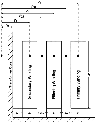
the primary winding is connected to a power source; the secondary winding is connected to a load; the filtering winding is connected to a filter; the secondary winding is arranged closest to the transformer core, followed by the filter winding and the primary winding; wherein the method comprising:
S1: designing an approximative zero-impedance for the filtering winding; wherein
an equivalent impedance of the filtering winding is calculated by:
 where Zk12, Zk13, and Zk23 are short-circuit impedance between the primary winding and the secondary winding, the primary winding and the filtering winding, and the secondary winding and the filtering winding, [−x, x] is an interval of approximative zero-impedance, x≤0.1%;
S2: relating transformer dimension parameters to the equivalent impedance of the filtering winding; wherein the short-circuit impedances are calculated by:
 where f is a fundamental frequency; I1 and N1 are rated current and turns of the primary winding; μ0 is absolute permeability, and
 H/m; ρ12, ρ13, ρ23 are Rogowski coefficients between the primary winding and the secondary winding, the primary winding and the filtering winding, and the secondary winding and the filtering winding, respectively; K is an additional reactance coefficient; ΣD12, ΣD13, ΣD23 are magnetic flux leakage areas between the primary winding and the secondary winding, the primary winding and the filtering winding, and the secondary winding and the filtering winding, respectively; e1 is an electric potential of each turn; H12, H13, H23, are arithmetic mean height of the primary winding and the secondary winding, the primary winding and the filtering winding, the secondary winding and the filtering winding, respectively;
the Rogowski coefficients are calculated by:
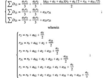
 the magnetic flux leakage areas are determined by:
 where r0 is transformer core radius; r1, r2, and r3 are center distances between the transformer core and the primary winding, the transformer core and the secondary winding and the transformer core and the filtering winding, respectively; r23 and r31 are center distances between the transformer core and air gaps; a1, a2, and a3 are winding thicknesses of the primary winding, the secondary winding, the filtering winding, respectively; a02, a23, and a31 are insulation distances between the transformer core and the secondary winding, the secondary winding and the filtering winding, the filtering winding and the primary winding, respectively;
S3: determining a minimum radial dimension of the inductive filtering transformer in the interval of approximative zero-impedance, to achieve an optimization of the transformer dimension parameters; wherein
the minimum radial dimension of the inductive filtering transformer is determined by following equation:
 |