| CPC G01M 13/00 (2013.01) [B30B 9/00 (2013.01); B30B 15/26 (2013.01)] | 4 Claims |

|
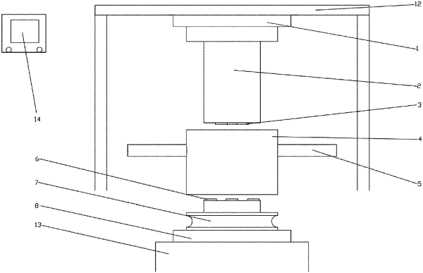
1. A piston press system for predicting roll service life of high-pressure grinding rolls, comprising a piston press and a piston mold, wherein
the piston press comprises a frame (12), a hydraulic piston (13) and a computer control system (14);
the piston mold comprises a piston head (2), a plurality of upper studs (3), a base (7), a plurality of lower studs (6), a cavity block (4), a first positioning block (9), a second positioning block (10), handles (5), an upper pressure plate (1), a lower pressure plate (8) and screw holes (11); wherein
the first positioning block (9) is fixedly connected with the piston head (2), the plurality of upper studs (3) are embedded in the piston head (2), and the plurality of upper studs (3) protrudes from a bottom surface of the piston head (2) by 3 millimeters (mm);
the plurality of studs (6) are embedded in the base (7), an upper part of the base (7) is provided with a bulge, and the plurality of lower studs (6) protrudes from the bulge of the base (7) by 3 mm;
the plurality of upper studs (3) are equal to the plurality of lower studs in height;
the piston head (2) and the upper pressure plate (1) are positioned through the first positioning block (9) and are fixed with bolts through the screw holes (11); the upper pressure plate (1) is fixedly connected with the frame (12);
the cavity block (4) has a through interior and is spliced with the bulge of the base (7);
the bulge is cylindrical in shape, having a diameter slightly smaller than an inner diameter of the cavity block (4), so that the cavity block (4) is tightly connected with the base (7);
press materials for a piston press test are loaded in a cavity formed by splicing the cavity block (4) and the base (7); and
a top of the lower pressure plate (8) is provided with a groove for fixing the second positioning block (10) so as to position and splice;
an outer side of the cavity block (4) is provided with the handles (5);
the second positioning block (10) is disposed at a center of the bottom of the base (7), and is fixedly connected with the base (7);
the lower pressure plate (8) is fixedly connected with the hydraulic piston (13), and the hydraulic piston (13) is externally connected with the computer control system (14);
wherein the computer control system (14) comprises a displacement sensor and a stress loader, and displacement data and stress data during the piston press test are obtained through the computer control system (14);
each of the displacement sensor and the stress loader is installed on the hydraulic piston (13) for data collection and transmits displacement and stress changes to the computer control system (14) by a signal line, and the computer control system (14) records the displacement data and the stress data in real-time.
|