| CPC F16F 7/00 (2013.01) [F16F 2228/06 (2013.01); F16F 2232/08 (2013.01)] | 7 Claims |
|
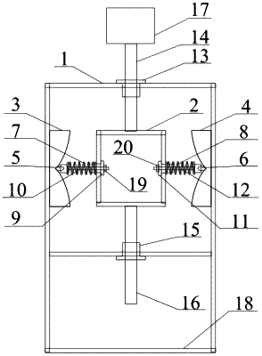
1. A zero-stiffness impact isolation device, comprising a cabinet body, wherein the device comprises a shell, an inner core, a first half-hourglass-shaped boss, a second half-hourglass-shaped boss, a first sliding block, a second sliding block, a first spring, a second spring, two transverse motion guide assemblies and two longitudinal motion guide assemblies, and the first half-hourglass-shaped boss and the second half-hourglass-shaped boss are fixedly connected to a left side wall and a right side wall of the shell respectively;
the transverse motion guide assemblies comprise a first linear bearing, a first sliding rod matched with the first linear bearing, a second linear bearing and a second sliding rod matched with the second linear bearing; the first linear bearing and the second linear bearing are fixedly connected with a left side wall and a right side wall of the inner core respectively, a left end of the first sliding rod and a right end of the second sliding rod are fixedly connected with the first sliding block and the second sliding block respectively, and a right end of the first sliding rod and a left end of the second sliding rod are both provided with external threads with predetermined lengths; the first spring sleeves on an outside surface of the first sliding rod, two ends of the first spring are respectively in contact with the first sliding block and the left side wall of the inner core, the second spring sleeves on an outside surface of the second sliding rod, and two ends of the second spring are respectively in contact with the second sliding block and the right side wall of the inner core;
the longitudinal motion guide assemblies comprise a third linear bearing, a third sliding rod matched with the third linear bearing, a fourth linear bearing and a fourth sliding rod matched with the fourth linear bearing; the third linear bearing and the fourth linear bearing are fixedly connected with an upper wall and an lower wall of the shell respectively, a lower end of the third sliding rod and an upper end of the fourth sliding rod are fixedly connected with an upper wall and a lower wall of the inner core respectively, an upper end of the third sliding rod is exposed out of the upper wall of the shell and fixedly connected with a separated object, and a lower end of the fourth sliding rod is a free end; and there are predetermined distances between the separated object and an upper surface of the upper wall of the shell as well as between the lower end of the fourth sliding rod and a mounting plane, and the predetermined distances are designed to ensure that a maximum stroke of the device is larger than a maximum movement amplitude of external impact load.
|