| CPC F16F 15/005 (2013.01) [F16F 13/00 (2013.01); F16F 15/022 (2013.01); F16F 2222/06 (2013.01); F16F 2224/0258 (2013.01); F16F 2224/0283 (2013.01); F16F 2228/066 (2013.01)] | 8 Claims |

|
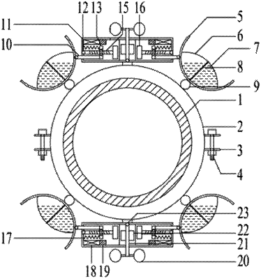
1. A magnetostriction-based vibration suppression apparatus for a steel pipe of a power transmission tower, comprising: a lantern ring (2), four spoiler cups (5), and two control boxes (11), wherein the lantern ring (2) is fixedly sleeved on the steel pipe (1); mouths of the spoiler cups (5) face outwards, and bottoms thereof are hinged on the lantern ring (2); the four spoiler cups (5) are squarely distributed with a center of the lantern ring (2) as a center; and the two control boxes (11) are symmetrically and fixedly mounted on the lantern ring (2);
wherein the control boxes (11) are arranged as follows: the spoiler cups (5) are arranged in pairs as a group, and each control box (11) is arranged between two spoiler cups (5); each control box (11) is provided therein with two groups of inerter units corresponding one-to-one to the spoiler cups (5) on both sides thereof;
wherein each group of the inerter units comprises a horizontally-arranged sliding rod (10), a horizontally-arranged ball screw (15), and a ball nut (13) and a flywheel (16) matched with the ball screw (15);
wherein one end of the ball screw (15) is rotatably mounted in the control box (11) via a bearing I (12), and the other end is fixedly mounted with the flywheel (16); the sliding rod (10) horizontally and slidably penetrates the control box (11); the sliding rod (10) is parallel to the ball screw (15); one end of the sliding rod (10) is connected to the ball nut (13), and the other end extends out of the control box (11) and hinged to the spoiler cups (5);
wherein each inerter unit is configured with a stiffness assembly, the stiffness assembly comprising a magnetically-controlled shape memory alloy spring (17), a coil (18), and a power supply control assembly (19) for power supply; the magnetically-controlled shape memory alloy spring (17) is parallel to the ball screw (15); one end of the magnetically-controlled shape memory alloy spring (17) is fixedly connected in the control box (11), and the other end is fixedly connected to the ball nut (13); the coil (18) is mounted in the control box (11) and faces the magnetically-controlled shape memory alloy spring (17); the power supply control assembly (19) is mounted in the control box (11) for supplying electric power to the coil (18); and
wherein the power supply control assembly (19) comprises a battery (26), an acceleration sensor (28), a controller (29), and a fuse (30), forming a closed circuit with the coil (18).
|