| CPC F01D 9/042 (2013.01) [F05D 2220/30 (2013.01); F05D 2240/128 (2013.01)] | 18 Claims |

|
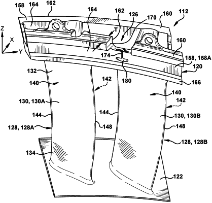
1. A turbine nozzle assembly, comprising:
at least one airfoil;
an outer endwall coupled to a radial outer end of the at least one airfoil;
a mounting rail coupled to the outer endwall, the mounting rail extending at least partially radially outward from the outer endwall and at least partially circumferentially along the outer endwall, the mounting rail having a radial outer surface, a rail thickness, and an origin at a rearwardmost point on a pressure side, circumferential end of the mounting rail; and
a stress relief structure in the mounting rail, the stress relief structure including an oblong opening defined through the rail thickness of the mounting rail, the oblong opening having a portion having a shape having a nominal profile defined by a plurality of arced surfaces defined substantially in accordance with Cartesian coordinate values of Y and Z and radius of curvature set forth in TABLE I, originating at the origin with positive values of Y and Z increasing with distance away from the at least one airfoil, a Y-axis extending in a circumferential direction parallel to an aft surface of the mounting rail, a Z-axis extending in a radial direction, and the shape projecting through the rail thickness of the mounting rail in a direction parallel to an X-axis of the turbine nozzle assembly, wherein the Cartesian coordinate values and the radius of curvature values are non-dimensional percentage values convertible to distances by multiplying the values by a minimum X-wise extent of the rail thickness of the mounting rail, and wherein Y and Z values are joined smoothly with one another to form a surface profile of the portion of the oblong opening through the rail thickness of the mounting rail in the direction parallel to the X-axis of the turbine nozzle assembly.
|