| CPC H02P 21/36 (2016.02) [D06F 34/10 (2020.02); D06F 37/40 (2013.01); H02P 3/18 (2013.01); H02P 27/06 (2013.01); D06F 34/08 (2020.02); D06F 2103/00 (2020.02); D06F 2103/46 (2020.02); D06F 2105/52 (2020.02)] | 18 Claims |

|
1. An appliance having a motor, the appliance comprising:
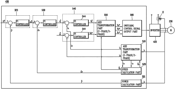
an inverter configured to transfer power applied from an input power source to the motor, the inverter comprising a plurality of pairs of switches, each pair of switches being electrically connected in series to each other and configured to generate a phase corresponding to the pair of switches; and
an inverter control unit configured to:
control operation of the inverter,
generate a braking command for stopping rotation of the motor in a preset braking time after the braking command is generated,
based on the braking command being generated, control the inverter to execute a first braking mode to thereby reduce a rotational speed of the motor in a state in which no current flows in the inverter control unit, and
based on execution of the first braking mode, control the inverter to execute at a second braking mode and a third braking mode to thereby reduce the rotational speed of the motor and stop rotation of the motor in a state in which a current flows in the inverter control unit,
wherein each pair of switches comprise an upper-arm switch and a lower-arm switch that are electrically connected in series to each other,
wherein the first braking mode is a redundant braking mode to be executed for a first time interval, the second braking mode is a plugging braking mode to be executed for a second time interval, and the third braking mode is a dynamic braking mode to be executed for a third time interval,
wherein the inverter control unit is configured to:
execute the first braking mode, the second braking mode, and the third braking mode according to a preset order,
in the second braking mode, control the inverter to generate a reverse phase current with respect to a rotating direction of the motor, and
in the third braking mode, turn off all of the upper-arm switches of the plurality of pairs of switches and turn on all of the lower-arm switches of the plurality of pairs of switches,
wherein the preset braking time corresponds to a sum of the first time interval, the second time interval, and the third time interval, and
wherein the inverter control unit is configured to set the third time interval based on an initial rotational speed of the motor at a time point at which the braking command is generated.
|