| CPC H02K 3/522 (2013.01) [H02K 7/083 (2013.01); H02K 7/145 (2013.01); H02K 11/0094 (2013.01); H02K 11/215 (2016.01); H02K 21/16 (2013.01); B25D 11/064 (2013.01); B25D 2250/095 (2013.01); H02K 2211/03 (2013.01)] | 6 Claims |

|
1. A power tool comprising:
a housing having a motor housing portion, a handle portion, and a battery pack interface, wherein the battery pack interface is configured to removably receive and support a battery pack;
a brushless direct current (DC) motor located within the motor housing portion and having a rotor and a stator, wherein the rotor is coupled to a motor shaft arranged to produce an output outside of the housing;
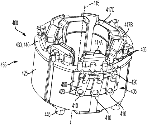
a non-conductive terminal mount located on an outer peripheral surface of the stator and including an angled surface, wherein the angled surface is not substantially parallel to a longitudinal axis of the motor; and
a plurality of terminals mounted on the angled surface of the terminal mount, wherein each of the terminals is angled in a first direction such that the terminals are not substantially parallel to the longitudinal axis of the motor;
wherein a first end of each of the terminals includes a tang loop configured to be electrically and physically connected to a stator coil;
wherein a second end of each of the terminals that is opposite the first end is electrically connected to a power source configured to provide power to the stator coil;
wherein the first end of each of the terminals is located closer to the longitudinal axis than the respective second end of each terminal; and
wherein each of the terminals is angled in a second direction different than the first direction and about a first respective axis through each of the terminals, the first respective axis being perpendicular to the longitudinal axis.
|