| CPC H02J 50/80 (2016.02) [H02J 50/12 (2016.02); H04B 5/0037 (2013.01); H04B 5/0081 (2013.01); H02J 50/60 (2016.02)] | 17 Claims |

|
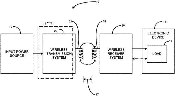
1. A wireless transmission system comprising:
a transmitter antenna configured for inductive coupling, via near-field magnetic coupling, with at least one other antenna of at least one other system and transmit alternating current (AC) wireless signals to the at least one other antenna, the AC wireless signals including wireless power signals and wireless data signals, the wireless data signals generated by altering electrical characteristics of the AC wireless signals at the at least one other system, the wireless power signals configured to provide electrical energy to a wireless power receiver system for charging or directly powering a load;
at least one sensor configured to detect a voltage of the wireless power signals associated with the electrical characteristics of the AC wireless signals;
a demodulation circuit including:
a slope detector circuit configured to (i) receive the voltage of the wireless power signals from the at least one sensor, (ii) detect a change in the voltage as a voltage rate of change, the slope detector circuit including a first operational amplifier (opamp) for slope detection to produce a slope detection signal comprising the voltage rate of change, and
a comparator circuit configured to (i) set a limit for a rising rate of change, (ii) receive the voltage rate of change, (iii) compare the voltage rate of change to the rising rate of change, (iv) determine that the voltage rate of change meets or exceeds a rise threshold, if the voltage rate of change meets or exceeds the rising rate of change, (v) determine if the voltage rate of change meets or exceeds one of the rise threshold or a fall threshold, (vi) if the voltage rate of change meets or exceeds one of the rise threshold or the fall threshold, generate a data alert, and (vii) and output a plurality of data alerts, wherein the comparator circuit includes a first digital potentiometer for setting the rising rate of change; and
a transmitter controller configured to (i) receive the plurality of data alerts from the demodulation circuit, (ii) decode the plurality of data alerts to determine the wireless data signals, and (iii) provide instructions for altering the rising rate of change to the first digital potentiometer.
|