| CPC H02J 50/005 (2020.01) [H01F 5/003 (2013.01); H01F 38/14 (2013.01); H02J 50/12 (2016.02); H02J 50/70 (2016.02); H02J 2310/48 (2020.01)] | 53 Claims |

|
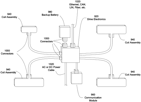
1. An inductive charger for transmitting power to an inductive receiver of an electronic device for charging the electronic device, the inductive charger comprising:
a first enclosure comprising metal and having an electrically non-conductive charging surface on a side of the first enclosure, the first enclosure comprising:
an inductive charging coil positioned behind the charging surface within the first enclosure,
wherein the inductive charging coil comprises a spiral-shaped metallic Litz wire conductor that defines two charging coil terminals,
wherein the inductive charging coil has a first side that faces the charging surface and a second side that faces away from the charging surface opposite the first side, and
wherein the inductive charging coil is configured to transmit electromagnetic power by inductive power transfer through the charging surface of the enclosure with an alternating magnetic field at an operating frequency when an electronic device is positioned in proximity to the charging surface; and
a metallic second enclosure physically separated from the first enclosure, the second enclosure comprising:
a drive circuit and a resonant capacitor electrically coupled to the inductive charging coil in the first enclosure to drive the inductive charging coil with an alternating current; and
a microcontroller electrically coupled to the drive circuit, wherein the microcontroller is configured to:
detect a received communication of information in a current or voltage modulation of the inductive charger coil by the inductive receiver; and
control the transmission of power during inductive power transfer; and
a shielded electrical cable that electrically couples the first enclosure and the second enclosure,
wherein the shielded electrical cable comprises two and only two sets of twisted wires coupling the drive circuit in the second enclosure to the two charging coil terminals of the inductive charging coil in the first enclosure to drive the inductive charging coil and to receive the communication of information from the inductive charging coil,
wherein each set of the two sets of twisted wires comprises multiple electrical wires to reduce electrical loss, and
wherein the shielded electrical cable comprises a metallic shield that covers the two sets of twisted wires and is coupled to an electrical ground;
wherein the second enclosure is not within the first enclosure.
|