| CPC H02G 1/1212 (2013.01) | 8 Claims |

|
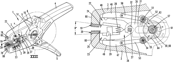
1. A wire stripper for stripping cables, comprising:
a fixed plier jaw having a fixed gripping part, a movable plier jaw rotatably connected to the fixed plier jaw, and a movable gripping part configured for moving the movable plier jaw,
two outer clamping jaws, one of said outer clamping jaws being disposed on the fixed plier jaw and the other of said outer clamping jaws being disposed on the movable plier jaw,
two inner cutting jaws, one of said inner cutting jaws engaging the fixed plier jaw and the other of said cutting jaws engaging the movable plier jaw,
a pull rod held captive within the fixed plier jaw and being connected to each of the two cutting jaws, and being actuatable by moving the movable gripping part toward the fixed gripping part,
wherein moving the movable gripping part toward the fixed gripping part causes the movable plier jaw to move toward the fixed plier jaw and causes the clamping jaws to move toward each other and the inner cutting jaws to move toward each other,
a sliding block fixed in each of the fixed plier jaw and movable plier jaw, each of the sliding blocks accommodating a sliding block part that is slidably movable along a respective one of the sliding blocks, wherein the sliding block parts are each connected via separate coupling rods to an adjustment part received in the fixed plier jaw,
wherein the cutting jaws, once being moved relative to each other are configured to be automatically linearly displaced from an extended starting position into a retracted end position by actuation of the pull rod, which moves the cutting jaws in a displacement direction (r) along the sliding block parts,
wherein the adjustment part is configured to manually adjust the cutting position of the cutting jaws independently of a closing position of the fixed plier jaw and movable plier jaw, such that manual actuation of the adjustment part adjusts a displacement of the sliding block parts along the sliding blocks in the displacement direction, so that a supporting point for guiding the cutting jaws on the sliding block parts may vary independently of the closing position of the fixed plier jaw and movable plier jaw in order to accommodate different thicknesses of insulation of the cables, and the sliding block parts are displaced in an equal amount in or opposite the displacement direction (r) via the coupling rods.
|