| CPC H01M 8/04753 (2013.01) [H01M 8/04097 (2013.01); H01M 8/04373 (2013.01); H01M 8/04388 (2013.01); H01M 8/04395 (2013.01); H01M 8/04425 (2013.01); F04D 27/0215 (2013.01); H01M 8/04302 (2016.02)] | 19 Claims |
|
1. A fuel cell control system, wherein the system comprises:
a reactor;
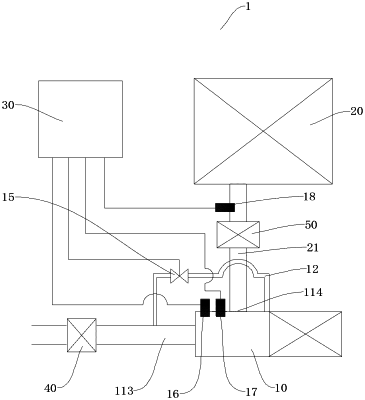
an air compressor, wherein the air compressor has a compressing cavity, the compressing cavity has a gas inlet and a gas outlet, a rotatable pressure wheel is disposed inside the compressing cavity, and the gas outlet is in communication with the reactor;
a control flow channel, wherein a first end of the control flow channel is in communication with a gas-intake side of the pressure wheel, a second end of the control flow channel is in communication with a wheel-back side of the pressure wheel, and the control flow channel is provided with a return valve for regulating a flow rate of the control flow channel; and
a central control unit, wherein the central control unit is communicatively connected to the return valve to control an opening degree of the return valve;
wherein the air compressor comprises:
a housing assembly, wherein the housing assembly has the compressing cavity, an installation cavity and a rotation-shaft cooperating cavity, and the rotation-shaft cooperating cavity is disposed between the compressing cavity and the installation cavity;
wherein the housing assembly comprises:
a pressing housing, wherein the pressing housing defines the compressing cavity;
a driving housing, wherein the driving housing defines the installation cavity; and
a back plate, wherein the back plate is disposed between the pressing housing and the driving housing, the back plate is located on the wheel-back side of the pressure wheel and forms a back-pressure gap with the pressure wheel, the driving housing is disposed on one side of the back plate that is opposite to the pressure wheel, and the back plate and the driving housing enclosure to form a thrust cavity; and
the back plate is provided with a first rotation-shaft hole, a second rotation-shaft hole is disposed inside the driving housing, a thrust bearing is disposed inside the thrust cavity, and the first rotation-shaft hole, the second rotation-shaft hole and the thrust cavity jointly define the rotation-shaft cooperating cavity.
|