| CPC G02B 7/003 (2013.01) [G02B 27/106 (2013.01); G02B 27/14 (2013.01); H01S 3/061 (2013.01); A61B 18/20 (2013.01); H01S 3/092 (2013.01); H01S 3/161 (2013.01); H01S 3/1616 (2013.01); H01S 3/1623 (2013.01); H01S 3/1643 (2013.01)] | 20 Claims |

|
1. A laser system, comprising:
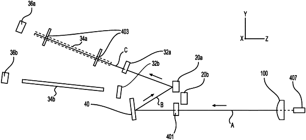
a first laser cavity configured to output a laser light along a first path;
a first mirror configured to receive the laser light from the first laser cavity, and redirect the laser light along a second path that is different than the first path;
a second mirror configured to receive the laser light from the first mirror, and redirect the laser light along a third path that is different than the first path and the second path;
a beam splitter located at a first position on the third path;
a beam combiner located at a second position on the third path; and
a coupling lens assembly, the coupling lens assembly including a lens located at a third position on the third path, wherein the coupling lens assembly is configured to move the lens in x-, y-, and x-directions.
|