| CPC G01K 11/324 (2021.01) | 2 Claims |

|
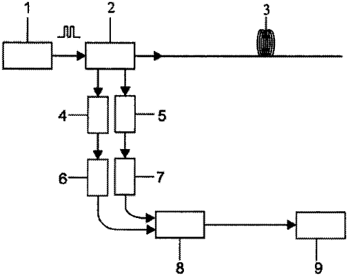
1. A high-precision temperature demodulation method oriented to a distributed fiber Raman sensor, characterized in comprising the following steps: Step 1: constructing a high-precision temperature detection device oriented to a distributed fiber Raman sensing system comprising a pulsed laser, an output end of the pulsed laser being connected to an input end of a Raman wavelength division multiplexer; two output ends of the WDM being respectively connected to input ends of a first Avalanche Photodiode (APD) and a second APD; an output end of the first APD being connected to an input end of a first Low-Noise Amplifier (LNA); an output end of the second APD being connected to an input end of a second LNA; output ends of the first LNA and the second LNA being connected to input ends of a data acquisition card; an output end of the data acquisition card being connected to an input end of a computer; a common end of the WDM being connected to an input end of a sensing fiber to be tested; Step 2: processing Stokes light and anti-Stokes light signals in a calibration stage transmitting laser pulses emitted by the pulsed laser to the sensing fiber to be tested; conducting spontaneous Raman scattering when the laser pulses propagate in a multi-mode sensing fiber, such that Stokes light and anti-Stokes light are generated at each position of the multi-mode sensing fiber; wherein backward Stokes light and anti-Stokes light generated in the fiber firstly respectively arrive at the first APD, the first LNA, and the second APD, the second LNA via the WDM, and are performed a photoelectric conversion and amplification, finally, enter the high-speed acquisition card and computer to acquire data to obtain positional and light intensity information of the Stokes light and anti-Stokes light along the fiber; before temperature measurement, performing a calibration processing for all of the sensing fiber to be tested at a constant temperature, and the calibration process being carried out twice in total in a calibration stage; in a first calibration stage, obtaining, by the data acquisition card, a backscattering light intensity curve of the anti-Stokes light and the Stokes light, whose light intensity ratio is expressed as:
 where Ks, Ka and Kr are coefficients related to a scattering end cross section of the fiber; Vs, Va and Vo are frequencies of the Stokes light, anti-Stokes light and incident light; h and k are Planck Constant and Boltzmann Constant respectively; 4v is a Raman frequency offset of the fiber, which is 13.2 THz; as, aa, ao are attenuation coefficients of the Stokes light, anti-Stokes light and Rayleigh scattering light per unit length of the fiber, respectively; Teo represents a temperature value of the sensing fiber to be tested in the first calibration stage; / represents a distance between the position and a front end of the multi-mode sensing fiber; and Po is intensity of incident light; in a second calibration stage, obtaining, by the data acquisition card, the backscattering light intensity curve of the anti-Stokes light and the Stokes light, whose light intensity ratio is expressed
as:
 where Tai represents the temperature value of the sensing fiber to be tested in the second calibration stage; Step 3: processing the Stokes light and anti-Stokes light signals in a measurement stage in the measurement stage, obtaining, by the data acquisition card, the backscattering light intensity curve of the anti-Stokes light and the Stokes light, whose light intensity ratio is expressed
as:
 where T represents the temperature value at a position 1 of the sensing fiber to be tested in the measurement stage; Step 4: a high-precision temperature demodulation method oriented to a distributed fiber Raman sensing system subtracting formula (1) from formula (3) to obtain:
 subtracting formula (2) from formula (3) to obtain:
ϕa/ϕs−ϕa1/ϕs1=KaVa4/KsVs4exp[(αs−αa)l]
 exp(−hΔv/kT)−exp(−hΔv/kTc1) exp(−hΔv/kT)−exp(−hΔv/kTc1) (5) (5)making a ratio of formula (4) to formula (5) to
obtain:
 resolving formula (6) to obtain:
 |