| CPC F16M 13/022 (2013.01) [F16C 11/04 (2013.01); G03B 17/561 (2013.01); F16M 2200/022 (2013.01)] | 19 Claims |

|
1. A joint component comprising:
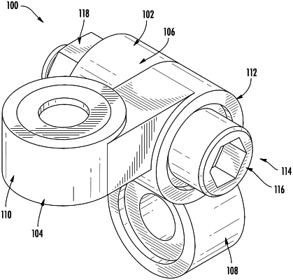
a first annular joint section defining a first axis, wherein a first peripheral section of the first annular joint section is defined to rotate about the first axis, and wherein each of a first peripheral surface and a second peripheral surface of the first annular joint section defines a respective recess defining the first axis; and
a second annular joint section fixedly coupled to the first annular joint section, the second annular joint section defining a second axis, wherein a second peripheral section of the second annular joint section is defined to rotate about the second axis, wherein the second axis is orthogonal to the first axis, and wherein each of a first peripheral surface and a second peripheral surface of the second annular joint section defines a respective recess defining the second axis.
|