| CPC F16D 3/50 (2013.01) [F16D 1/10 (2013.01); F16D 2001/103 (2013.01); Y10S 464/90 (2013.01); Y10T 403/472 (2015.01); Y10T 403/475 (2015.01); Y10T 403/7033 (2015.01)] | 17 Claims |

|
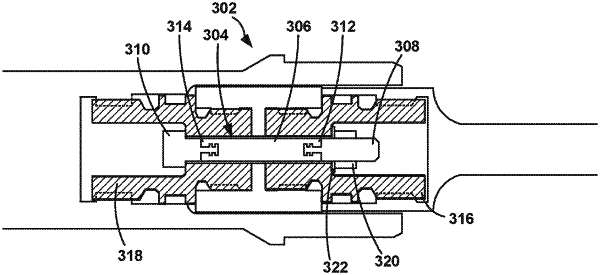
1. An electrically insulated shaft coupling comprising:
a first metallic portion, wherein the first metallic portion comprises a first plurality of splines configured to position within a first cavity of a first rotating shaft and interface with splines of the first rotating shaft;
a second metallic portion, wherein the second metallic portion comprises a second plurality of splines configured to position within a second cavity of a second rotating shaft and interface with splines of the second rotating shaft;
an electrically insulating portion that separates the first metallic portion and the second metallic portion; and
an axial connector extending from a first end positioned in the first cavity to a second end positioned in the second cavity, wherein the axial connector is configured to axially retain the first and second metallic portions relative to each other.
|