| CPC F02D 17/02 (2013.01) [F01M 1/02 (2013.01); F02B 75/18 (2013.01); F02B 77/14 (2013.01); F02F 1/18 (2013.01); H02K 7/1884 (2013.01); H02K 33/16 (2013.01); H02K 53/00 (2013.01); F02B 63/04 (2013.01); F02B 2075/1832 (2013.01); H01T 13/00 (2013.01)] | 9 Claims |

|
1. An engine, comprising:
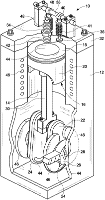
an engine block having at least one cylinder bank including a plurality of cylinder bores formed therein;
a piston reciprocatingly disposed in each of the cylinder bores;
a crankshaft rotatably mounted to the engine block; a plurality of connecting rods having a first end and a second end, the first end rotatably attached to the crankshaft and the second end coupled to the piston;
a cylinder head mounted to the at least one cylinder bank and covering the cylinder bores, the cylinder head including an intake valve and an exhaust valve in fluid communication with each of the cylinder bores;
at least one permanent magnet disposed in a skirt of each piston;
at least one electromagnet positioned adjacent to the at least one permanent magnet; and
a control system selectively providing an electrical current to the electromagnets to produce a desired magnetic field, wherein the magnetic field of the electromagnets cooperates with a magnetic field of the permanent magnets to affect a motion of the piston in respect of the engine block, wherein:
the at least one electromagnet being disposed in at least one of: the engine block, the cylinder head,
a brace coupled to the engine block, and an oil pan mounted to a lower end of the engine block, and wherein: the connecting rods are magnetized.
|