| CPC F02B 67/06 (2013.01) [F16H 55/36 (2013.01); F16H 2007/0865 (2013.01)] | 4 Claims |

|
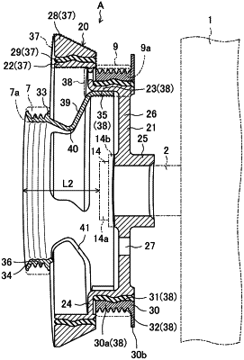
1. An engine crank pulley structure disposed at a vehicle front side of a longitudinal engine, the structure comprising:
a front pulley that transmits a crank rotational force to a first accessory via a belt;
a rear pulley that is disposed at a vehicle rear side of the front pulley and transmits the crank rotational force to a second accessory via a belt;
a connecting portion that connects the front pulley and the rear pulley, the connecting portion crushing and deforming in a vehicle front-rear direction as a collision load toward the vehicle rear side is applied to the connecting portion; and
an inertia ring between the front pulley and the rear pulley, wherein
an outer diameter of the front pulley is smaller than an inner diameter of the rear pulley,
the connecting portion has a V-shape protruding radially inward,
the connecting portion includes a through-hole, and
an inner diameter of the inertia ring is larger than an outer diameter of the rear pulley.
|