| CPC E21B 43/128 (2013.01) [E21B 31/00 (2013.01); E21B 33/12 (2013.01); E21B 34/06 (2013.01); E21B 2200/05 (2020.05)] | 14 Claims |

|
1. A wellbore system comprising:
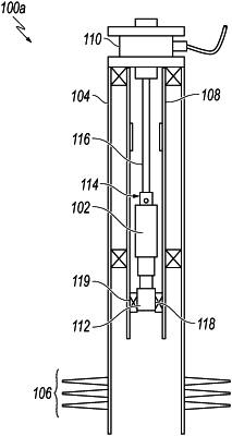
a cable extending into a wellbore from a topside facility, the cable comprising electrical lines, hydraulic lines, and a support structure configured to support tooling at a downhole end of the cable;
an electric submersible artificial lift system at the downhole end of the cable, the electric submersible artificial lift system comprising:
an electric motor;
a fluid end coupled to and configured to be driven by the electric motor; and
a shear interconnect at an uphole end of the electric submersible artificial lift system, the shear interconnect configured to shear the cable between the electric submersible artificial lift system and the topside facility, the shear interconnect configured to shear the cable at the electric submersible artificial lift system;
a packer defining a receptacle configured to receive the electric submersible artificial lift system; and
a safety valve arranged to cease flow within the wellbore when the safety valve is in a closed position,
wherein the hydraulic lines are configured to actuate the safety valve and inject chemicals into a production stream.
|