| CPC E05B 47/0006 (2013.01) [E05B 47/0038 (2013.01); E05B 47/0611 (2013.01); E05B 47/0673 (2013.01); E05B 2047/0092 (2013.01); E05Y 2201/42 (2013.01); E05Y 2201/462 (2013.01); E05Y 2900/132 (2013.01)] | 19 Claims |

|
1. An electromechanical lock comprising:
an electronic circuit configured to read data from an external source and match the data against a predetermined criterion;
an actuator comprising a permanent magnet arrangement movable from a locked position to an open position by electric power; and
an access control mechanism configured to be rotatable by a user;
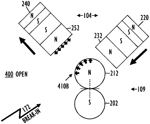
wherein in the locked position, the permanent magnet arrangement is configured and positioned to create and direct a near magnetic field to block the access control mechanism from rotating, and simultaneously the permanent magnet arrangement is configured and positioned to create and attenuate a range and a magnitude of the near magnetic field towards a far magnetic break-in field originating from outside of the electromechanical lock, whereas
in the open position, the permanent magnet arrangement is configured and positioned to create and direct a reversed near magnetic field to release the access control mechanism to rotate, and simultaneously the permanent magnet arrangement is configured and positioned to create and attenuate a range and a magnitude of the reversed near magnetic field towards the far magnetic break-in field,
wherein the access control mechanism comprises one or more movable magnetic pins configured and positioned to block the access control mechanism from rotating when affected by the near magnetic field, and configured to release the access control mechanism to rotate when affected by the reversed near magnetic field,
wherein the permanent magnet arrangement comprises a first axis between poles, and the magnetic pin comprises a second axis between poles, and the first axis is transversely against the second axis both in the locked position and in the open position,
wherein the one or more movable magnetic pins comprise a main permanent magnet configured and positioned to interact with the permanent magnet arrangement, and an auxiliary permanent magnet configured and positioned to attenuate a magnetic field of the main permanent magnet towards the far magnetic break-in field,
wherein in transitioning from the locked position to the open position, the permanent magnet arrangement begins to rotate in relation to the one or more movable magnetic pins of the access control mechanism, causing movement of the one or more movable magnetic pins,
wherein the one or more movable magnetic pins comprise first and second movable magnetic pins,
wherein in the locked position, the near magnetic field pushes the first magnetic pin to obstruct rotation of the access control mechanism and pulls the second magnetic pin to decouple the rotation from the access control mechanism,
wherein in the open position, the reversed near magnetic field pulls the first magnetic pin to release the rotation of the access control mechanism and pushes the second magnetic pin coupling the rotation of the access control mechanism with the access control mechanism, and
wherein the second magnetic pin moves during the transition from the locked position to the open position.
|