| CPC D05B 29/12 (2013.01) [D05B 27/04 (2013.01)] | 11 Claims |

|
1. An upper feed device comprising:
a main body portion configured to be mounted to a presser bar of a sewing machine, the main body portion having an upper feed dog, a first mounting portion, and a second mounting portion, the upper feed dog being configured to convey an object to be sewn in conjunction with up and down movement of a needle bar of the sewing machine, the first mounting portion having a first groove opening downward, and the second mounting portion having a second groove opening downward, and
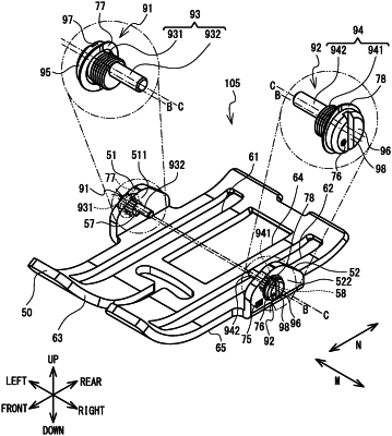
a presser foot configured to be detachably mounted to the main body portion, the presser foot having a presser plate, a first opposing portion, a second opposing portion, a first pin, a first protruding portion, a second pin, and a second protruding portion, an opening through which the upper feed dog is inserted being formed in the presser plate, the first opposing portion extending upward from the presser plate on one side of the opening in the lateral direction of the opening, the first pin protruding on a side with the opening from the first opposing portion, and being configured to rotatably fit into the first groove of the first mounting portion, the first protruding portion protruding on an opposite side to the side with the opening from the first opposing portion, the second opposing portion extending upward from the presser plate on another side of the opening opposite from the first opposing plate, in the lateral direction of the opening, and facing the first opposing portion, the second pin protruding on a side with the opening from the second opposing portion, and being configured to rotatably fit into the second groove of the second mounting portion, the second protruding portion protruding on an opposite side to the side with the opening from the second opposing portion, wherein
in a longitudinal direction of the opening, an extension range of the first protruding portion overlaps with an extension range of the first pin, and an extension range of the second protruding portion overlaps with an extension range of the second pin,
at least a portion of each of the first protruding portion, the first pin, the second protruding portion, and the second pin are provided along a same axis extending in the lateral direction of the opening,
a first hole passing through in the lateral direction of the opening is formed in the first opposing portion,
the first pin and the first protruding portion are integrally formed, and have a first insertion portion to be inserted into the first hole and a first fitting portion to be fit into the first groove,
a second hole passing through in the lateral direction of the opening is formed in the second opposing portion,
the second pin and the second protruding portion are integrally formed, and have a second insertion portion to be inserted into the second hole and a second fitting portion to be fit into the second groove,
an axial center of the first insertion portion extending in the lateral direction of the opening differs from an axial center of the first fitting portion extending in the lateral direction of the opening, and
an axial center of the second insertion portion extending in the lateral direction of the opening differs from an axial center of the second fitting portion extending in the lateral direction of the opening.
|