| CPC B60L 53/126 (2019.02) [B60L 53/38 (2019.02); H01F 1/10 (2013.01); H01F 38/14 (2013.01); H02J 50/10 (2016.02); H02J 50/90 (2016.02); Y02T 10/70 (2013.01); Y02T 10/7072 (2013.01); Y02T 90/12 (2013.01); Y02T 90/14 (2013.01)] | 4 Claims |

|
1. A method for the supply of an electrical component with electric power using an inductive charging system having a primary coil unit and a secondary coil unit, wherein the electrical component is connected to the secondary coil unit and wherein the primary coil unit comprises:
a primary coil and a primary ferrite,
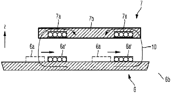
wherein the primary coil is not rigidly connected to the primary ferrite such that the primary coil is moveable relative to the primary ferrite from a starting position for an electromagnetic coupling between the primary coil unit and the secondary coil unit to a charging position for the electromagnetically coupling,
wherein the primary coil unit incorporates a plurality of ferrite elements,
wherein the plurality of ferrite elements are arranged relative to the primary ferrite, such that the primary ferrite, along a periphery of the primary ferrite, is entirely enclosed by the plurality of ferrite elements,
wherein the plurality of ferrite elements comprises groups and sub-groups of ferrite elements, wherein the primary coil unit, for each respective sub-group of ferrite elements, incorporates a respective ferrite suspension device for the constituent ferrite elements of the sub-group, and
wherein one group of ferrite elements comprises a plurality of sub-groups of ferrite elements, wherein the primary coil unit, for each respective group of ferrite elements, comprises a ferrite element control unit, by which the respective ferrite suspension devices of the constituent sub-groups of ferrite elements in the group are controllable, in order to fold away or fold out the ferrite elements in a sub-group;
the method comprising the acts of:
setting a rough position of the secondary coil unit relative to the primary coil unit to establish the electromagnetic coupling between the primary coil unit and the secondary coil unit;
displacing the primary coil in the primary coil unit relative to the primary ferrite in the primary coil unit in a preferred direction, from the starting position of the primary coil to the charging position of the primary coil, such that an electromagnetic coupling factor of the rough position of the secondary coil unit relative to the primary coil unit is increased, wherein the preferred direction lies in a plane of a planar basic shape of the primary ferrite; and
changing a magnetically active surface area within the primary coil unit in the plane of the planar basic shape of the primary ferrite by folding away into the plane of the planar basic shape of the primary ferrite the ferrite elements in a group by the respective ferrite element control unit or by folding out of the plane of the planar basic shape of the primary ferrite the ferrite elements in the group by the respective ferrite element control unit.
|