| CPC B21B 39/14 (2013.01) [B21B 1/24 (2013.01); B21B 13/02 (2013.01)] | 9 Claims |

|
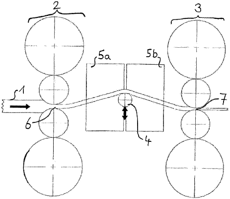
1. A finishing train for a metal strip, the train having at least two roll stands and at least one loop lifter which is disposed between two neighboring ones of the roll stands;
the loop lifter is located between the roll stands, and is configured to be height-adjustable to a topmost vertical position and a lower vertical position for changing a lifted position of metal strip passing the loop lifter at a respective path of the strip;
at least one device for laterally guiding a moving metal strip past the loop lifter which is between the two roll stands, the at least one device for lateral guiding comprising at least one main member module extending in a direction toward one of the roll stands and in a direction toward the loop lifter; the at least one main member module having a substantially vertically oriented guiding plane;
a plurality of wear members, each wear member is rotatable to a plurality of rotary positions for the respective wear member;
each wear member having a wear face, the wear faces of the wear members are substantially planar and are substantially parallel to the guiding plane; and
at least two of the wear members are disposed between one of the roll stands and the loop lifter;
with the loop lifter at the topmost vertical position, a path is defined for the metal strip that passes along each wear surface; and
with the loop lifter at the lower vertical position, another path is defined for the metal strip that passes along each wear surface.
|