| CPC B03C 1/286 (2013.01) [B03C 1/0332 (2013.01); B03C 2201/18 (2013.01)] | 20 Claims |

|
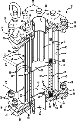
1. A pneumatically-operated magnetic separator, comprising:
a housing wall;
a first flange plate assembly located adjacent an end of said housing wall, said first flange plate assembly including a first flange plate and a second flange plate, a plurality of first openings located in said second flange plate;
a second flange plate assembly located adjacent another end of said housing wall, said second flange plate assembly including a third flange plate and a fourth flange plate, a plurality of second openings located in said fourth flange plate;
a main fluid passage established in part by said housing wall, by said first flange plate assembly, and by said second flange plate assembly;
a plurality of tubes extending between said first flange plate assembly and said second flange plate assembly, said plurality of tubes received in said plurality of first openings of said second flange plate and in said plurality of second openings of said fourth flange plate, each of said plurality of tubes having a bore;
a plurality of shuttles situated in said bores of said plurality of tubes, each of said plurality of shuttles including at least one magnet, said plurality of shuttles longitudinally moveable within said bores;
an internal baffle plate located within said main fluid passage and extending laterally and radially across said main fluid passage, said internal baffle plate dividing said main fluid passage into a first compartment and a second compartment, a plurality of recesses residing around a periphery of said internal baffle plate and establishing fluid-flow paths between said internal baffle plate and said housing wall for process fluid flow from said first compartment and to said second compartment; and
a plurality of first weldments attaching said plurality of tubes and said first flange plate assembly together, and a plurality of second weldments attaching said plurality of tubes and said second flange plate assembly together;
wherein said second flange plate has a first surface in confrontation with said first flange plate, each of said plurality of tubes has a first terminal end, and said plurality of first weldments is established at said first surface and said first terminal ends, wherein said fourth flange plate has a second surface in confrontation with said third flange plate, each of said plurality of tubes has a second terminal end, and said plurality of second weldments is established at said second surface and said second terminal ends, wherein said plurality of first weldments are a plurality of first tungsten inert gas (TIG) weldments, wherein said plurality of second weldments are a plurality of second tungsten inert gas (TIG) weldments, wherein a first bevel edge is provided at first open end edges of each of said plurality of first openings, said plurality of first TIG weldments located at said first bevel edges, and wherein a second bevel edge is provided at second open end edges of each of said plurality of second openings, said plurality of second TIG weldments located at said second bevel edges.
|