| CPC B01D 35/1475 (2013.01) [B01D 24/10 (2013.01); B01D 35/30 (2013.01); C02F 1/001 (2013.01); B01D 2201/162 (2013.01); B01D 2201/301 (2013.01); B01D 2201/307 (2013.01); C02F 2103/44 (2013.01); C02F 2201/005 (2013.01); C02F 2201/006 (2013.01)] | 6 Claims |

|
1. A method of operating a fluid purification device, comprising:
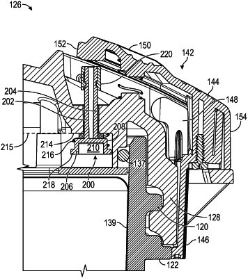
biasing a relief valve into a non-operational position, the relief valve providing a fluid path between a hollow interior of a tank of the fluid purification device and an exterior of the fluid purification device, the relief valve having a valve member and a cup portion arranged at an end of the valve member within the hollow interior, the cup portion including a recessed area on one end and a first seal on an opposite end, an opening of the recessed area facing the hollow interior of the tank;
transforming the relief valve to an operational position wherein the first seal is in sealing contact with a surface of the hollow interior of the tank in response to the tank being filled with a fluid, wherein a portion of the relief valve is positioned within the hollow interior in both the non-operational position and the operational position;
pressurizing the hollow interior during operation;
de-pressuring the hollow interior; and
unlocking a cover in response to moving the relief valve to a released position.
|