| CPC A61M 5/30 (2013.01) [A61M 2205/42 (2013.01); A61M 2240/00 (2013.01); A61M 2250/00 (2013.01)] | 3 Claims |

|
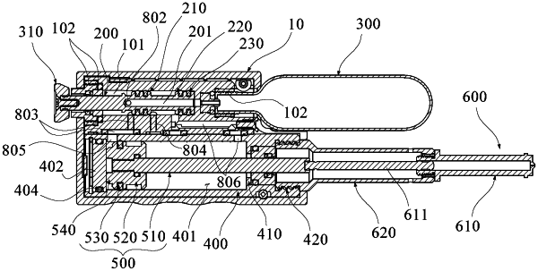
1. A needleless pain-free injection device comprising:
a valve body having an internal space in a longitudinal direction of the valve body;
a valve member slidably provided in the internal space of the valve body, the valve member having a plurality of protruding parts formed on an outer circumference of the valve member to airtightly slide along an inner wall of the valve body;
a liquefied gas container detachably coupled to the valve body such that the liquefied gas container and the valve member are arranged on the same central axis, the liquefied gas container comprising a nozzle at an opening to communicate with the internal space of the valve body;
an operating knob provided at an end of the valve member exposed from the valve body;
a cylinder body coupled to one side of the valve body and closed at one end of the cylinder body, the cylinder body having an internal space in a longitudinal direction of the cylinder body;
a piston member slidably provided in the internal space of the cylinder body and including
a piston head configured to slide along an inner surface of the cylinder body,
a piston rod extending from one side of the piston head, and
a cushion member formed at the other side of the piston head to prevent the piston head from directly colliding with the cylinder body;
an injection unit detachably coupled to the cylinder body and having an injection piston rod coupled to the piston rod in a contact or fitting manner;
a first communication hole for allowing the internal space of the valve body to communicate with outside air;
a second communication hole formed in the valve member for allowing the internal space of the valve body to communicate with an elongated groove of the valve member;
a first switching communication path formed at a first side of the valve body and configured to communicate with or block an internal space on the first side of the valve body according to the sliding of the valve member;
a second switching communication path formed at a second side of the valve body and configured to establish or block communication of an internal space on the second side of the valve body with the first communication hole according to the sliding of the valve member;
an inlet communication path formed in the cylinder body for allowing the first switching communication path to communicate with a first internal space of the cylinder body, the first internal space of the cylinder body being a space between a cylinder body cap and the piston head,
an outlet communication path formed in the cylinder body and the valve body for allowing the second switching communication path to communicate with a second internal space of the cylinder body, the second internal space of the cylinder body being a space between the piston head and a guide partition wall,
wherein when the valve member moves forward, a gas discharged from the liquified gas container moves through, in sequence, the second communication hole, the internal space of the valve body, the first switching communication path, the inlet communication path, and the first internal space of the cylinder body, to strike the piston head, thereby moving forward the piston member.
|