| CPC A61H 3/00 (2013.01) [A61H 1/0244 (2013.01); B25J 9/0006 (2013.01); B25J 11/00 (2013.01); B25J 11/009 (2013.01); A61H 2001/0248 (2013.01); A61H 2003/007 (2013.01); A61H 2201/1215 (2013.01); A61H 2201/149 (2013.01); A61H 2201/163 (2013.01); A61H 2201/1621 (2013.01); A61H 2201/1642 (2013.01); A61H 2201/1652 (2013.01); A61H 2201/1659 (2013.01); A61H 2201/5007 (2013.01); A61H 2201/5069 (2013.01); A61H 2201/5084 (2013.01); A61H 2230/625 (2013.01)] | 15 Claims |

|
1. A wearable assist robot apparatus, comprising:
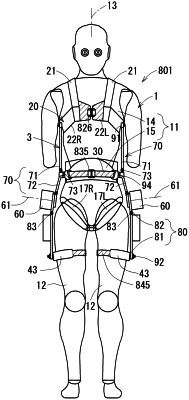
a harness device to be worn and retained by a wearer;
an assist drive mechanism provided on the harness device, including at least one drive source configured to be disposed on each of left and right sides of a lower body trunk of the wearer configured to generate drive torque about an axial line in a lateral direction of the wearer, the assist drive mechanism being configured to apply assisting force moments respectively to portions of the wearer between the body trunk and respective left and right thighs by drive torque from the respective drive sources;
a pair of angle sensors configured to detect relative angles between the body trunk and the respective left and right thighs of the wearer about the axial line in the lateral direction;
at least one processor configured to
determine a foot landing state in response to an output from the angle sensors; and
in response to outputs from the respective angle sensors and a determined foot landing state, apply an assisting force moment in a direction of support to a supporting leg in a landed state by a supporting-leg side drive source of the at least one drive source, and apply a swing-up force moment in a swing-up direction to a free leg not in contact with the land by a free-leg side drive source of the at least one drive source,
wherein after the assisting force moments are maintained at a first predetermined value for a first predetermined time, the assisting force moments are reduced in proportion to respective angles detected by the pair of angle sensors, and
after the swing-up force moment is maintained at a second predetermined value for a second predetermined time, the swing-up force moment is reduced at a predetermined speed.
|