| CPC A61B 6/027 (2013.01) [A61B 6/032 (2013.01); A61B 6/035 (2013.01); A61B 6/04 (2013.01); A61B 6/4447 (2013.01); A61B 6/4452 (2013.01); A61B 6/504 (2013.01); A61B 6/508 (2013.01)] | 18 Claims |

|
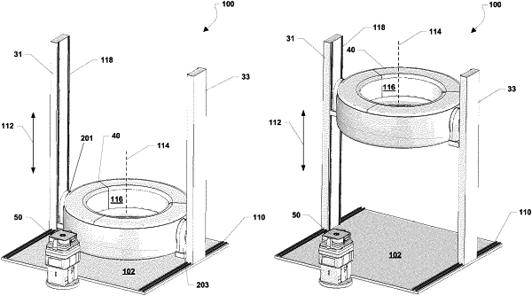
1. A multi-directional x-ray imaging system, comprising:
a gantry defining a central imaging bore and an imaging axis extending through the central imaging bore, the gantry including a housing;
an x-ray source component and an x-ray detector component for obtaining x-ray images of an object located within the central imaging bore, the x-ray source component and the x-ray detector component being supported for rotation within the housing of the gantry;
a support column located on a side of the gantry and supporting the gantry, with the support column having at least one vertical rail extending vertically along the support column, wherein the gantry is moveable along the at least one vertical rail of the support column and pivotable relative to the support column between:
a first configuration in which the imaging axis of the gantry is in a vertical orientation, and
a second configuration in which the imaging axis of the gantry is in a horizontal orientation;
a base having a horizontal guide extending horizontally along the base, wherein the support column extends in a vertical direction from the base and is moveable on the horizontal guide along the base;
a first drive mechanism arranged to move the gantry on the at least one vertical rail along the support column; and
a second drive mechanism arranged to move the support column and the gantry via the horizontal guide along the base.
|