| CPC A61B 18/1815 (2013.01) [A61B 18/1445 (2013.01); A61B 17/320068 (2013.01); A61B 18/1206 (2013.01); A61B 18/16 (2013.01); A61B 2017/320082 (2017.08); A61B 2018/0063 (2013.01); A61B 2018/00077 (2013.01); A61B 2018/00083 (2013.01); A61B 2018/00095 (2013.01); A61B 2018/00178 (2013.01); A61B 2018/00196 (2013.01); A61B 2018/00345 (2013.01); A61B 2018/00404 (2013.01); A61B 2018/00589 (2013.01); A61B 2018/00595 (2013.01); A61B 2018/00601 (2013.01); A61B 2018/00607 (2013.01); A61B 2018/00982 (2013.01); A61B 2018/00994 (2013.01); A61B 2018/126 (2013.01); A61B 2018/1452 (2013.01); A61B 2018/1455 (2013.01); A61B 2018/162 (2013.01); A61B 2018/165 (2013.01); A61B 2018/183 (2013.01); A61B 2018/1823 (2013.01); A61B 2018/1876 (2013.01); A61B 2018/1892 (2013.01)] | 20 Claims |

|
1. An electrosurgical vessel sealer comprising:
an instrument shaft comprising a coaxial transmission line for conveying microwave electromagnetic (EM) energy;
a distal end assembly arranged at a distal end of the instrument shaft to receive the microwave EM energy from the instrument shaft, the distal end assembly comprising:
a pair of jaws that are movable relative to each other to open and close a gap between opposing inner surfaces thereof; and
a blade for cutting through biological tissue,
wherein the pair of jaws comprise an energy delivery structure arranged to emit the microwave EM energy into the gap between the opposing inner surfaces,
wherein the energy delivery structure comprises a traveling wave antenna structure mounted on the inner surface of one or both of the pair of jaws, the traveling wave antenna structure being arranged to confine an emitted microwave field substantially within a region between the pair of jaws,
wherein the blade is slidably disposed within the distal end assembly to be movable through the region between the pair of jaws; and
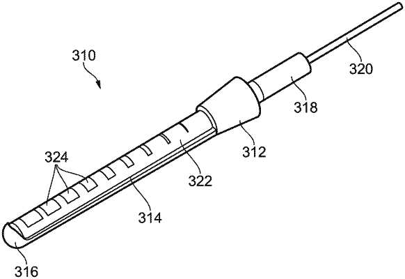
wherein the travelling wave antenna structure comprises a coaxial cable, a housing for retaining a distal end portion of the coaxial cable, and a conductive ground tube provided within the housing and into which the distal end portion of the coaxial cable is inserted, the coaxial cable comprising:
an inner conductor,
a dielectric material surrounding the inner conductor, and
an outer conductor surrounding the dielectric material, the outer conductor of the distal end portion of the coaxial cable having been removed,
the conductive ground tube comprising a plurality of windows formed in the conductive ground tube to expose the dielectric material of the coaxial cable, and the conductive ground tube and the distal portion of the coaxial cable forming a coaxial travelling wave antenna.
|