| CPC A43C 11/008 (2013.01) [A43B 3/34 (2022.01); A43B 3/36 (2022.01); A43B 3/44 (2022.01); A43B 5/00 (2013.01); A43B 11/00 (2013.01); A43C 7/08 (2013.01); A43C 11/165 (2013.01)] | 19 Claims |

|
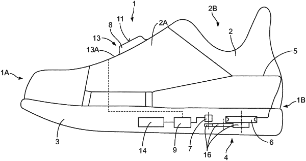
1. A shoe, in particular a sports shoe that includes a heel region and a forefoot region, and, comprising:
an upper part having a medial side and a lateral side, and defining a heel cavity,
a sole which is connected with the upper part,
a rotary closure for fastening the shoe on a wearer's foot by means of at least one tensioning element, wherein the rotary closure comprises a rotatably arranged tensioning roller for winding the tensioning element, wherein the tensioning roller is driven by means of an electric motor, and
a switching element which is arranged at the instep and which is connected to control means, wherein the switching element and the control means can actuate the electric motor,
wherein the switching element is formed by a number of capacitive sensors which are arranged one beside the other which form a surface which is accessible to a user,
wherein the switching element is located at the instep between the forefoot region and the heel region, and between the lateral side and the medial side and entirely forward of the heel cavity of the upper, and
wherein the switching element includes a plurality of illumination elements.
|