| CPC A24F 40/46 (2020.01) [A24F 40/40 (2020.01); A24F 40/485 (2020.01); A61M 11/042 (2014.02); A61M 15/008 (2014.02); A61M 15/06 (2013.01); A24F 40/10 (2020.01); A61M 2205/3331 (2013.01); A61M 2205/3653 (2013.01); A61M 2205/8206 (2013.01)] | 20 Claims |

|
1. A cartridge system, comprising:
a liquid storage portion comprising a housing configured to hold a liquid aerosol-forming substrate;
a mouthpiece having an outlet opening at a proximal end thereof and being removably connected to a first end of the liquid storage portion; and
a heater assembly comprising:
an electrical heating element configured to heat the liquid aerosol-forming substrate to form an aerosol, and
a porous capillary material comprising a ceramic or a ceramic-based material and having a first face being in physical contact with at least a portion of the electrical heating element, the porous capillary material being configured to convey the liquid aerosol-forming substrate to the electrical heating element by capillary action,
the electrical heating element being disposed across the first face of the porous capillary material,
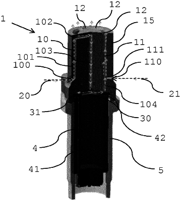
wherein the liquid storage portion is disposed at a first side of the heater assembly and a first airflow channel is disposed at a second side of the heater assembly, a portion of the first airflow channel defining an airflow path that extends in a direction perpendicular to the first face of the porous capillary material and is directed at a center of the electrical heating element, and
wherein at least a portion of a second airflow channel extends from the heater assembly to the outlet opening of the mouthpiece via a central channel of the housing.
|