| CPC H03K 3/027 (2013.01) [H03K 19/20 (2013.01)] | 15 Claims |

|
1. A circuit, comprising:
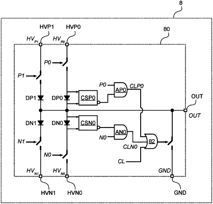
a set of first input pins configured to receive respective positive voltage signals at a plurality of different positive voltage levels;
a set of second input pins configured to receive respective negative voltage signals at a plurality of different negative voltage levels;
a reference input pin configured to receive a reference voltage signal intermediate the positive voltage signals and the negative voltage signals;
an output pin configured to supply a pulsed output signal; and
control circuitry configured to:
selectively couple the output pin to one of the first input pins, the second input pins and the reference input pin to generate the pulsed output signal at the output pin;
selectively couple at least one of the second input pins and the reference input pin to the output pin during falling transitions of the pulsed output signal between two positive voltage levels of the plurality of different positive voltage levels;
selectively couple at least one of the first input pins and the reference input pin to the output pin during rising transitions of the pulsed output signal between two negative voltage levels of the plurality of different negative voltage levels; and
during falling transitions of the pulsed output signal between two positive voltage levels of the plurality of different positive voltage levels, sense a current flowing between the output pin and the first input pin currently coupled thereto, and decouple the output pin from the second input pins and the reference input pin in response to the sensed current flowing between the output pin and the first input pin currently coupled thereto being higher than a first threshold value.
|