| CPC H02P 27/06 (2013.01) [H02J 9/062 (2013.01)] | 14 Claims |

|
1. A variable frequency drive system comprising:
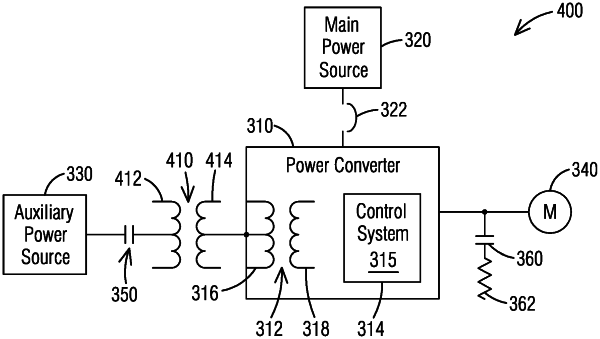
a power converter comprising a plurality of power cells supplying power to one or more output phases,
a main power source configured to provide main input power to the power converter,
an auxiliary power source configured to provide auxiliary input power to the power converter, and
a control system in communication with the power converter and controlling operation of the plurality of power cells,
wherein the control system comprises at least one processor and is configured via computer executable instructions to
detect a main input voltage drop of the main power source below a predefined power threshold,
disconnect the main power source in response to the main input voltage drop, and
enable the auxiliary power source to provide auxiliary input power to the power converter in response to the main input voltage drop,
further comprising a first contactor arranged between the auxiliary power source and the power converter, wherein the auxiliary power source is connected to the power converter via the first contactor in response to the main input voltage drop,
further comprising a second contactor arranged between the power converter and an output load of the power converter, wherein the control system is further configured to close the second contactor when the power converter reaches a predefined value of its nominal input voltage, wherein regenerated power is diverted to a resistive load bank when the second contactor is closed,
wherein the control system is further configured to:
when a frequency of the output load corresponds to essentially zero (0) Hertz (Hz):
open the second contactor,
open the first contactor,
connect the main power source to the power converter, and
energize the power converter.
|