| CPC H02M 3/04 (2013.01) [H03K 5/24 (2013.01); G06F 1/26 (2013.01); H03K 2005/00058 (2013.01)] | 20 Claims |

|
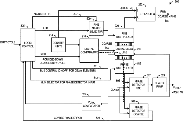
1. A direct current (DC) to DC (DC-DC) converter comprising:
a comparator configured to set a pulse width of a signal pulse, the pulse width corresponding to a voltage level of an output voltage of the DC-DC converter;
a digital delay line (DDL) operatively coupled to the comparator, the DDL configured to adjust the pulse width of the signal pulse by linearly introducing delays to the signal pulse, wherein the DDL comprises a linear sequence of delay elements;
a multiplexer operatively coupled to the DDL, the multiplexer configured to selectively output a delayed version of the signal pulse;
a phase detector operatively coupled to receive a system clock on a system clock line and the multiplexer, the phase detector configured to generate a phase error based on a received output of the multiplexer and the received system clock on the system clock line; and
a logic control circuit operatively coupled to the multiplexer and the DDL, the logic control circuit configured to adjust a delay introduced to the signal pulse in accordance with the phase error, wherein the logic control circuit is configured to deactivate delay elements of the linear sequence of delay elements not configured to introduce the delay to the signal pulse.
|