| CPC H02K 3/522 (2013.01) [H02K 5/1732 (2013.01); H02K 5/225 (2013.01); H02K 7/003 (2013.01); H02K 7/083 (2013.01); H02K 21/16 (2013.01); B60T 13/745 (2013.01); H02K 2203/09 (2013.01)] | 6 Claims |

|
1. A hollow shaft motor, comprising:
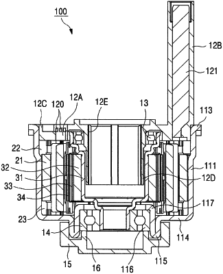
a housing (11) having a cylindrical shape;
an upper cover (12) coupled to an upper portion of the housing (11);
a lower cover (15) coupled to a lower portion of the housing (11);
a stator assembly (20) located in the housing (11); and
a rotor assembly (30) located in the stator assembly (20) to rotate,
wherein the rotor assembly (30) comprises a hollow shaft (31), a rotor core (32) coupled to an outer circumference of the hollow shaft (31), and a plurality of magnets (33) attached to an outer circumference of the rotor core (32), and
the upper cover (12) comprises a bus bar receiving part (12A) in which a bus bar (120) is installed,
wherein the housing (11) has a lower protruding part (115) being formed with bent and folded to reinforce strength by a pressing process, wherein a bent portion of the lower protruding part (115) is folded by directly contacting with each other,
wherein a lower bearing (14) is press-fitted and coupled to an inner surface of the lower protruding part (115),
wherein a stopper (16) is interposed between the lower bearing (14) and the lower cover (15),
wherein the lower protruding part (115) is located in a space formed between an outer circumferential surface of the stopper (16) and in inner circumferential surface of the lower cover (15),
wherein the stopper (16) supports a lower surface of lower bearing (14) and is coupled to an inner circumferential surface of the lower protruding part (115).
|