| CPC H02J 7/345 (2013.01) [H02J 7/0063 (2013.01)] | 20 Claims |

|
1. A power control system, comprising:
an AC power mains;
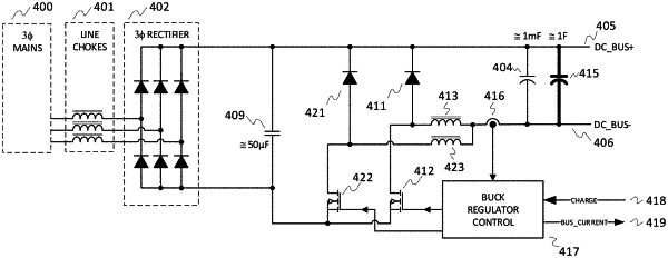
an input bridge rectifier connected to the AC power mains, the input bridge rectifier having: an upper output rail coupled to an upper DC bus rail; and a lower output rail;
a buck regulator circuit including:
a transistor switch coupled in power output-receiving relationship to the lower output rail of the input bridge rectifier;
a free-wheeling diode connected to a drain of the transistor switch and extending between the drain and the upper output rail; and
an inductor coupled in a power output-receiving relationship to the drain of the transistor on a first side and to the lower DC bus rail on a second side;
a first capacitor extending between the upper output rail and lower DC bus rail that is in parallel with a DC power output bus, the first capacitor receiving current from the buck regulator circuit for initial charging and storing excess regenerative power for subsequent use; and
a current sensor connected in series with the buck regulator circuit to directly sense an instantaneous current in the inductor of the buck regulator circuit, the instantaneous current indicative of an incremental change of charge transfer to the first capacitor,
wherein:
the transistor switch is controlled, based on the instantaneous current sensed in the inductor, to limit peak output current to the DC power output bus and thus limit the input current and power from the AC power mains.
|