| CPC H01Q 15/168 (2013.01) [H01Q 1/42 (2013.01)] | 2 Claims |
|
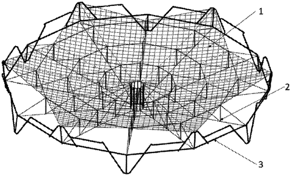
1. A deployable mesh antenna based on dome-type tensegrity, comprising: a wire mesh reflector, a dome-type reflector support system, and a peripheral deployable truss which are coaxially arranged;
wherein the peripheral deployable truss comprises: an annular main rod and a plurality of truss units disposed on the main rod, and the plurality of truss units are connected end to end;
wherein an outermost cable boundary of the dome-type reflector support system is fixedly connected to the peripheral deployable truss, the dome-type reflector support system comprises: an inner strut ring and a plurality of radial rib units connected to an outer circumference of the inner strut ring, each of the plurality of radial rib units is arranged at a radial direction of the inner strut ring, and the plurality of radial rib units are connected through hoop cables;
wherein the wire mesh reflector is covered on the dome-type reflector support system to form a parabolic structure, the wire mesh reflector is petal-shaped and has a grid structure;
wherein the inner strut ring comprises a plurality of inner ring rods parallel to one another and distributed in a circular shape, top ends of the plurality of inner ring rods are connected in series through a cable, and bottom ends of the plurality of inner ring rods are connected in series through a cable;
wherein each radial rib unit comprises a plurality of back cables arranged at a same straight line, the plurality of back cables are sequentially connected with the bottom end of a corresponding one of the plurality of inner ring rods, the plurality of back cables are located at a radial direction of a ring surrounded by the bottom ends of the plurality of inner ring rods; an end of each back cable facing away from the corresponding inner ring rod is provided with a strut, a bottom end of the strut is fixedly connected to the back cable, and two adjacent struts in the same radial rib unit are connected through a diagonal cable, and the top end of the inner ring rod and the bottom end of the strut closest to the inner ring rod are connected through a diagonal cable;
wherein in the two adjacent struts of the same radial rib unit, a top end of the strut closer to the inner strut ring is connected with an end of the diagonal cable, and the bottom end of the strut farther away from the inner strut ring is connected with another end of the diagonal cable;
wherein a distance between the two adjacent struts in the same radial rib unit increases outward from the inner strut ring, and a length of the strut in the same radial rib unit increases outward from the inner strut ring, the top ends of the struts in the plurality of radial rib units fall on a same paraboloid, and the top ends of the struts located on a same circumference in the plurality of radial rib units are connected in series by the hoop cable;
wherein each truss unit comprises a retractable lower sleeve rod connected with the main rod, and further comprises a left half unit and a right half unit which take the retractable lower sleeve rod as an axis and are in an axisymmetric structure; the left half unit comprises a retractable upper sleeve rod, an upper auxiliary rod, a connecting rod and a lower auxiliary rod connected sequentially in that order; two ends of the retractable upper sleeve rod are respectively hinged with an end of the upper auxiliary rod and the main rod, another end of the upper auxiliary rod is hinged with the main rod, two ends of the retractable lower sleeve rod are respectively hinged with the main rod and an end of the lower auxiliary rod, an end of the connecting rod is hinged on a middle of the upper auxiliary rod, another end of the lower auxiliary rod is hinged with another end of the connecting rod, a position of one third of a length of the lower auxiliary rod is hinged with the main rod, the retractable upper sleeve rod and the retractable lower sleeve rod are located on upper and lower sides of the main rod, and the retractable upper sleeve rod and the retractable lower sleeve rod are parallel to the strut, the upper auxiliary rod of the left half unit is hinged with the upper auxiliary rod of the right half unit in the adjacent truss unit; the retractable upper sleeve rods connected by the two hinged upper auxiliary rods is the same retractable upper sleeve rod, and hinged positions of the two hinged upper auxiliary rods and the retractable upper sleeve rod are the same hinged point;
wherein the peripheral deployable truss is provided with a driving cable passing through the plurality of truss units individually; in the left half unit of each truss unit, a connection position of the retractable upper sleeve rod and the main rod, a connection position of the retractable upper sleeve rod and the upper auxiliary rod, a connection position of the upper auxiliary rod and the main rod, a connection position of the retractable lower sleeve rod and the main rod, and a connection position of the retractable lower sleeve rod and the lower auxiliary rod are respectively provided with fixed pulleys, and the driving cable passes through the upper auxiliary rod and successively bypasses the fixed pulleys of the truss unit; in the right half unit of each truss unit, a connection position of the retractable upper sleeve rod and the main rod, a connection position of the retractable upper sleeve rod and the upper auxiliary rod, a connection position of the upper auxiliary rod and the main rod, and a connection position of the lower auxiliary rod and the main rod are respectively provided with fixed pulleys, and the driving cable is set in a same way in the plurality of truss units; and two ends of the driving cable are connected to a motor;
wherein a center of the wire mesh reflector is provided with a center opening matching with the inner strut ring, the center opening is fixed connected with the top ends of the plurality of inner ring rods, grids of the wire mesh reflector are radially distributed around the center opening, and sizes of the grids increase from the center opening to an outer edge of the wire mesh reflector, and each grid is an isosceles trapezoid, and upper and lower bottom edges of the isosceles trapezoid grid are respectively fixed on two adjacent hoop cables; and
wherein the outer edge of the wire mesh reflector is provided with a tension cable, the tension cable is arranged in multiple V-shapes, the multiple V-shapes are sequentially connected along an outline of the outer edge of the wire mesh reflector, and a V-shaped connection point of each V-shape of the tension cable is fixed at a connection point of the two upper auxiliary rods of the peripheral deployable truss.
|