| CPC H01J 37/3211 (2013.01) [H01J 37/32183 (2013.01); H01J 37/32825 (2013.01); H01J 2237/327 (2013.01)] | 10 Claims |

|
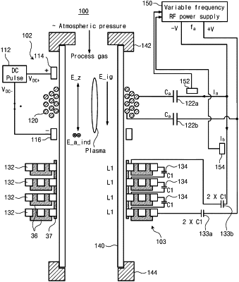
1. A plasma generating apparatus, comprising:
a dielectric tube configured to provide a space for plasma and comprising a first inlet at one end of the dielectric tube and an outlet at another end of the dielectric tube;
a first antenna module surrounding an outer side wall of the dielectric tube and comprising two terminals;
two first capacitors connected to the first antenna module,
wherein one first capacitor is serially connected to one terminal of the first antenna module, and
wherein another first capacitor is serially connected to another terminal of the first antenna module;
a second antenna module surrounding the outer side wall of the dielectric tube and comprising two terminals,
wherein the first antenna module is closer to the first inlet than the second antenna module and the second antenna module is closer to the outlet than the first antenna module, and
wherein an inductance of the first antenna module is smaller than an inductance of the second antenna module;
two second capacitors connected to the second antenna module,
wherein one second capacitor is serially connected to one terminal of the second antenna module, and
wherein another second capacitor is serially connected to another terminal of the second antenna module; and
a RF generator configured to provide a RF power with the first antenna module or the second antenna module,
wherein the RF power is provided to the first antenna module via the two first capacitors and is provided to the second antenna module via the two second capacitors,
wherein the RF generator is configured to provide a first RF power of a first frequency to the first antenna module via the two first capacitors and provide a second RF power of a second frequency to the second antenna module via the two second capacitors, and
wherein the first frequency is different from the second frequency.
|