| CPC H01J 35/16 (2013.01) [H01J 35/045 (2013.01); H01J 35/064 (2019.05)] | 20 Claims |
|
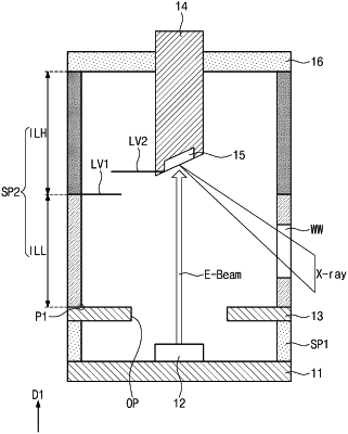
1. An X-ray tube, comprising:
a first electrode;
a second electrode spaced apart from the first electrode;
a target disposed in a lower portion of the second electrode;
an emitter disposed on the first electrode;
a third electrode which is positioned between the first electrode and the second electrode and comprising an opening at a position perpendicularly corresponding to the emitter; and
a spacer provided on the third electrode and surrounding the second electrode,
wherein the spacer comprises a first section located adjacent to the third electrode and a second section disposed on the first section,
wherein the spacer comprises a ceramic insulator and conductive dopants dispersed within the ceramic insulator,
wherein a concentration of the conductive dopants in the first section of the spacer is greater than a concentration of the conductive dopants in the second section,
wherein the third electrode is in contact with the first section of the spacer, and
wherein the first electrode comprises a cathode electrode, the second electrode comprises an anode electrode and the third electrode comprises a gate electrode.
|