| CPC G06T 7/0004 (2013.01) [G01N 29/0663 (2013.01); G01N 29/2418 (2013.01); G06F 3/14 (2013.01)] | 19 Claims |

|
1. A defect inspection apparatus comprising:
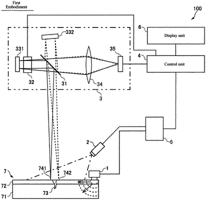
an excitation unit configured to excite an elastic wave to an inspection target;
a laser illumination unit configured to emit laser light onto the inspection target;
an interference unit configured to cause laser light reflected at different positions of the inspection target excited by the excitation unit to interfere with each other;
an imaging unit configured to acquire an image of the interfered laser light; and
a control unit configured to acquire a vibration state based on a plurality of still images acquired by the imaging unit and generate a moving image related to propagation of an elastic wave of the inspection target,
wherein the control unit is configured to perform control to identify a measurement inappropriate region in which the vibration state has not been correctly acquired, based on an imaging result by the imaging unit and display the measurement inappropriate region in such a manner as to be distinguishable from a measurement appropriate region, and
wherein the control unit is configured to perform control to identify a region in which a light quantity of the interfered laser light acquired by the imaging unit is insufficient or excessive to correctly acquire the vibration state by the control unit, as the measurement inappropriate region.
|