| CPC G03F 7/70775 (2013.01) | 20 Claims |

|
1. An object positioning system including:
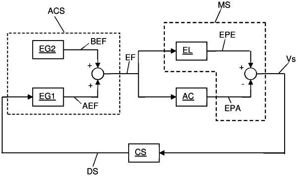
an actuator system; and
a measurement system,
wherein the actuator system comprises an actuator made of a material with predominantly electrostrictive properties and substantially no net polarization in absence of an electric field,
wherein the actuator system is configured to apply an electric field to the actuator, the electric field comprising a bias electric field and an actuation electric field superimposed on the bias electric field, a field strength of the actuation electric field being equal to or smaller than a field strength of the bias electric field,
wherein the measurement system is configured to measure an electrical property of the actuator that is representative of a mechanical state of the actuator,
wherein the measurement system comprises a bridge circuit including an actuator and a reference element having electrical properties matched to the electrical properties of the actuator,
wherein the actuator system is configured to apply a same electric field to the actuator and the reference element, and
wherein the bridge circuit is configured to output a signal representative of a difference in behavior between the actuator and the reference element.
|