| CPC G02B 27/0176 (2013.01) [G02B 27/0179 (2013.01)] | 16 Claims |

|
1. A wearable display device, comprising: a motor, a processor, and a motor drive assembly; wherein
the processor is connected to the motor drive assembly, and is configured to receive a motor control instruction and send the motor control instruction to the motor drive assembly, wherein the motor control instruction carries at least one of a rotation mode and a speed control parameter;
the motor drive assembly is connected to the motor, and is configured to: control the motor to rotate based on the rotation mode in the case that the motor control instruction carries the rotation mode, and adjust a rotation speed of the motor based on the speed control parameter in the case that the motor control instruction carries the speed control parameter; and
the motor, upon rotating, is configured to adjust a position of an imaging face of the wearable display device; wherein
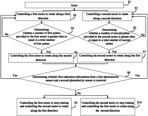
the rotation mode comprises one of forward rotation, reverse rotation, reciprocation, reset, and stop, the wearable display device comprises a first motor and a second motor; and the drive circuit in the motor drive assembly comprises a first drive sub-circuit and a second drive sub-circuit; wherein in the case that the rotation mode in the motor control instruction is the reciprocation, the controller is configured to:
provide a first mode control signal to the first drive sub-circuit and provide a second mode control signal to the second drive sub-circuit in the case that the first motor rotates to an initial position and the second motor rotates to the initial position;
provide the second mode control signal to the first drive sub-circuit in the case that a number of first pulses provided to the first motor is greater than or equal to a total number of first pulses in the process of rotation of the first motor from the initial position along a first direction; and provide the first mode control signal to the second drive sub-circuit in the case that a number of second pulses provided to the second motor is greater than or equal to a total number of second pulses in the process of rotation of the second motor from the initial position along a second direction; and
control the first motor to stop rotating and control the second motor to rotate along the first direction when receiving first indication information from a first photoelectric sensor corresponding to the first motor, and not receiving first indication information from a second photoelectric sensor corresponding to the second motor; control the second motor to stop rotating and control the first motor to continue to rotate along the second direction when receiving the first indication information from the second photoelectric sensor corresponding to the second motor, and not receiving the first indication information from the first photoelectric sensor corresponding to the first motor; simultaneously control the first motor and the second motor to rotate along opposite directions when receiving the first indication information from the first photoelectric sensor corresponding to the first motor and the first indication information from the second photoelectric sensor corresponding to the second motor;
the first drive sub-circuit is configured to control, based on the first mode control signal, the first motor to rotate along the first direction, and control, based on the second mode control signal, the first motor to rotate along the second direction; and the second drive sub-circuit is configured to control, based on the second mode control signal, the second motor to rotate along the second direction, and control, based on the first mode control signal, the second motor to rotate along the first direction;
wherein the first direction and the second direction are opposite, the total number of the first pulses is a number of pulses provided by the motor drive assembly to the first motor in the case that the first motor rotates from the initial position to an end position, and the total number of the second pulses is a number of pulses provided by the motor drive assembly to the second motor in the case that the second motor rotates from the initial position to the end position, wherein the initial position and the end position are two limit positions to which the motor rotates.
|